| Front Page |  |
| Deployment | |
| Aesthetic | |
| Refurbishing | |
| Connecting | |
| Communicating | |
| Manuals | |
| Rentals | |
| Supplies | |
| About Aetheric |
Connecting a Teletype Model 15 to a Personal Computer
The Teletype Model 15 was designed for a rather different electrical interface than one finds today. The device uses a 60 millampere "current loop", based on telegraph technology used from the 1870s onward.
To connect this machine to a modern personal computer, one must provide a suitable connecting device. We have developed one built from modern components.
This device connects to an RS-232 serial port. If you need to connect to a USB port, see Connecting a Teletype to a Universal Serial Bus (USB) port.
We do not sell these boards. We have, however, made the design freely available.
The design files to replicate this printed circuit board can be obtained via this link. The design is in the formats used by ExpressPCB. A parts list using entirely parts which can be ordered from Digi-Key is also provided.
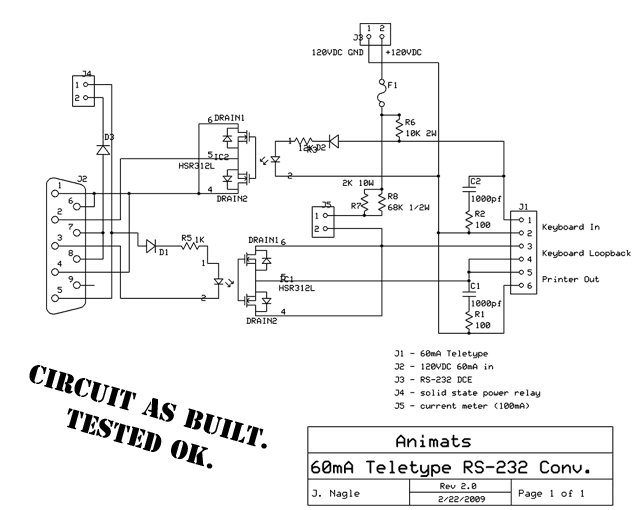 |
| Circuit design for the electrical interface device |
This is a simple level converter. Its electrical connections are as follows.
| Connector | Pin | Function |
|---|---|---|
J1 |
1 | Keyboard jack(Tip) |
| 2 | Keyboard jack (Ring) | |
| 3 | Keyboard test jack (Tip) | |
| 4 | Keyboard test jack (Ring) | |
| 5 | Printer jack(Tip) | |
| 6 | Printer jack (Ring) | |
J2 |
1 | Data Carrier Detect (not used) |
| 2 | Receive Data (from keyboard) | |
| 3 | Transmit Data (to printer) | |
| 4 | Data Terminal Ready (must be ON) | |
| 5 | Ground | |
| 6 | Data Set Ready (not used) | |
| 7 | Request to Send (turns on motor) | |
| 8 | Clear to Send (not used) | |
| 9 | Ring Indicator (not used) | |
| J3 (120 VDC power) |
1 | High voltage ground |
| 2 | +120 VDC | |
| J4 (Motor control) |
1 | Ground |
| 2 | +12 to solid state relay | |
J5 |
1 | -, to 100ma meter, or jumper to 2 |
| 2 | + to 100mA meter, or jumper to 1 |
On the left, at J2, is a standard RS-232 port. On the right, at J1, a connection for a 60mA Teletype current loop. The loop is powered from a 120 volt DC supply attached to connector J3. J4 and J5 provide optional features. A current meter can be attached at J4 (which must otherwise be shorted). J5 provides an output from the Request to Send line of the RS-232 connection, which we use to control a solid state relay, and thence power to the Teletype's motor.
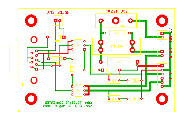 |
| Printed circuit board for the electrical interface device |
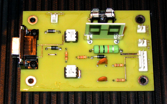 |
| The actual board, after construction |
- The large, flat, upright object is a 2,000 ohm, 10 watt thick film resistor. This type of resistor can run hot without overheating the PC board. The more common ceramic and wirewound resistors are not suitable for printed circuit board mounting at this wattage level. This board requires ventilation. Do not seal it in an unvented case - it will overheat.
- The board is divided into a low voltage section, to the left of the two opto-isolators, and a high voltage section, to the right. To maintain this division, the opto-isolators face in opposite directions.
- This board is powered from the Data Terminal Ready line of the RS-232 port. For the receive section of the board to operate, the RS-232 port at the computer end must set DTR to ON.
- The transmit side of the board requires an RS-232 signal which goes negative during marking. Most standard RS-232 ports do this.
- The signal output by the device as Receive Data does not go negative. This violates the RS-232 standard but will work with most serial ports. We did this to avoid the need for an external 5 volt power supply.
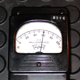 |
60 millampere current loop The unit is designed to deliver 60mA to a Teletype with a 55 ohm selector magnet. It does. |
We have two of these devices working. Other than the annoying level of heat dissipated by the 10 watt resistor, they perform satisfactorily.
Update: July 23, 2012
The Fairchild HSR-312L opto-isolator used in the original design is now obsolete. The Omron G3VM-401B is a pin-compatible replacement with better specifications and has been successfuly used (by Steve Garrison) with this board design.
December 31, 2015